Last time on the weather channel
Faulty data collection with Python and Rust lead me to the real problem: the hardware. I am not an electrical engineer, I thought doing the math that all the sensors run on 3.3 volts and draw less amps than the Pi 5’s 3.3v rail can support meant everything would work. Just wire up all the matching wires on the Pi’s GPIO pins to the sensors and call it a day. Turns out I was wrong.
A slightly deeper dive into low voltage design
The internet suggested I add decoupling capacitors to prevent noise from one circuit from impacting the other sensors. I2C is a serial communication protocol and all sensors share the same Serial Data Line (SDA) and Serial Clock Line (SCL) pins. All the sensors need to play nicely with each other and not mess each other up. The theory being while one sensor was communicating with the Pi another sensor could start pulling more power which would cause the communication to fail for the first sensor. The internet and AI recommended I add 0.1µF and 100µF capacitors before each sensor’s vin and ground.
The second recommended fix was adding
pull-up resistors. These are
needed because the SDA/SCL lines are
open drain and the sensors can
only pull the voltage down, the pull-up resistors are needed to pull the signal
up so there is a clear distinction between the low and high values. The theory
is the signal could be getting stuck in an intermediate value which causes
issues in the protocol like this:
Sensor pmsa003i poll failed (attempt 1): Failed to read PMSA003I sensor: BadChecksum.
Again I went with the recommended 2.2K ohm resistor for the SDA/SCL lines.
New parts
I couldn’t find a store near me that had the parts (RIP Fry’s) so as silly as it was I put in one more order at Adafruit (TODO get sponsored). The way these parts get wired in didn’t make a lot of sense and initially felt wrong. The capacitors went right next to the sensors in parallel (not series) with the sensors. The pull up resistors are in parallel not series (TODO ask an electrical engineer to ELI5).
Fitting everything on the breadboard required re-wiring everything one more
time. 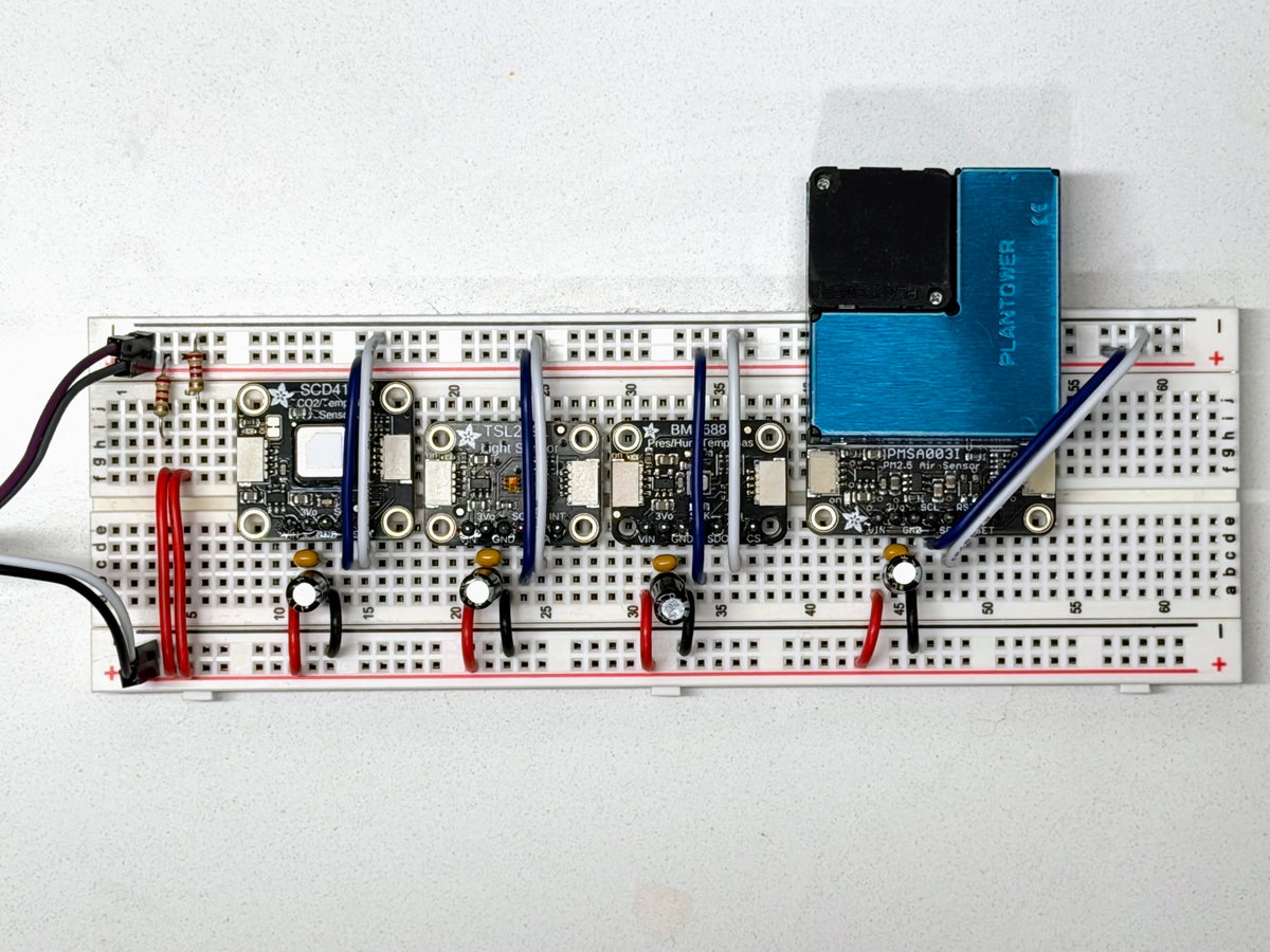
Success?
With the new capacitors and resistors everything seems to be working and stable for the past few hours. Time will tell if it’s finally solved.